Overview
A smart farm is a system that applies sensors and communications (IoT), data analytics, and AI to agriculture (crops, livestock, and aquaculture) to automatically monitor and control the environment, thereby increasing productivity and quality while reducing water, energy, and labor. Among these, the automatic irrigation system is designed to keep soil moisture within a hysteresis-based target range, with minimum on-time and cooldown intervals enforced on the pump to prevent excessive switching and overheating. Measurement signals are smoothed (filtered) to reduce noise, all state changes and sensor readings are logged over serial, and a button allows manual override when necessary. Additional sensors such as temperature/humidity and flow/level can be integrated, and cloud logging can be extended for remote monitoring and analysis, enabling the end-to-end loop of “measurement → decision → pump control → record” to operate reliably and transparently.
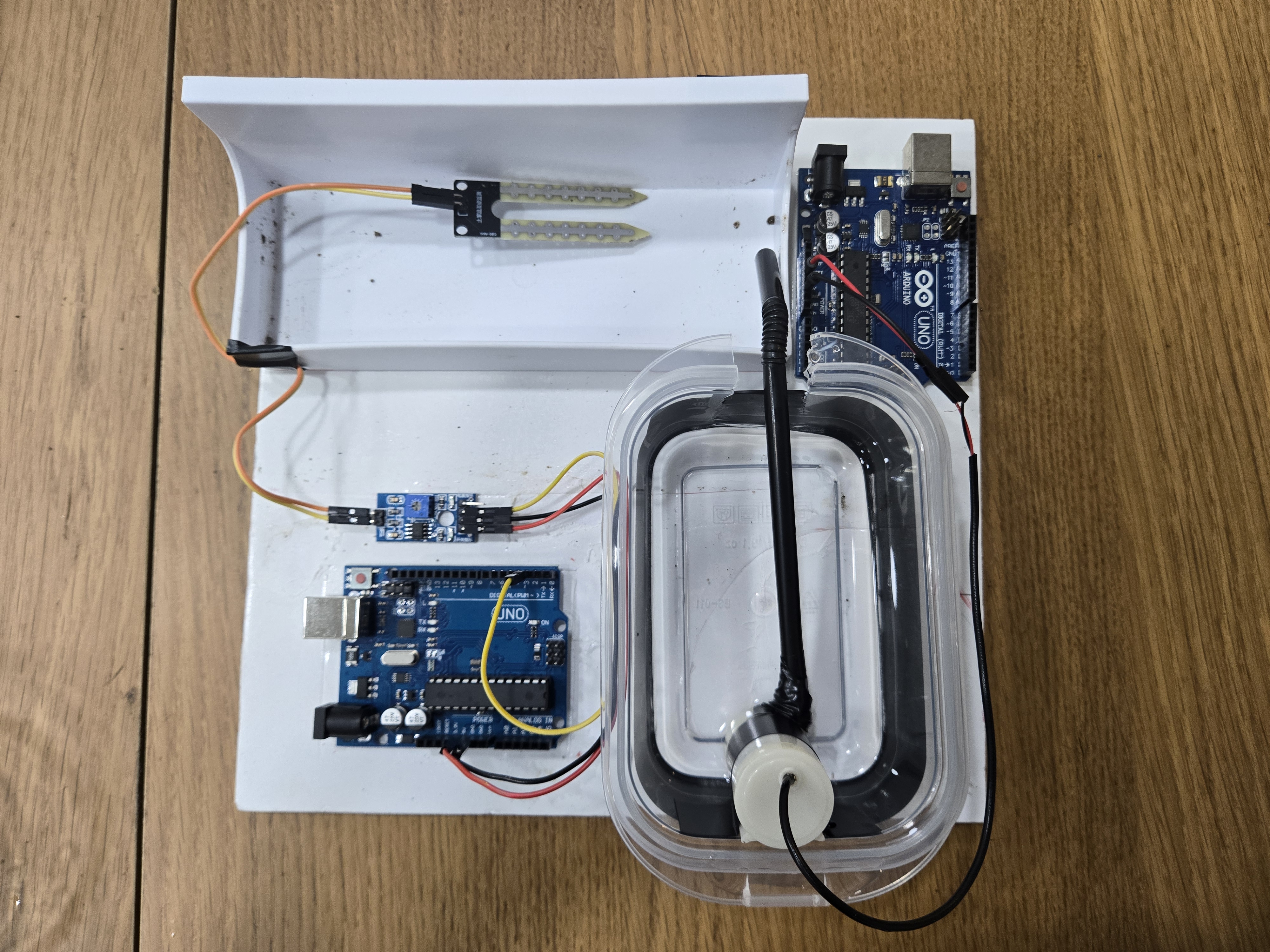
Reference Images
1. Scope
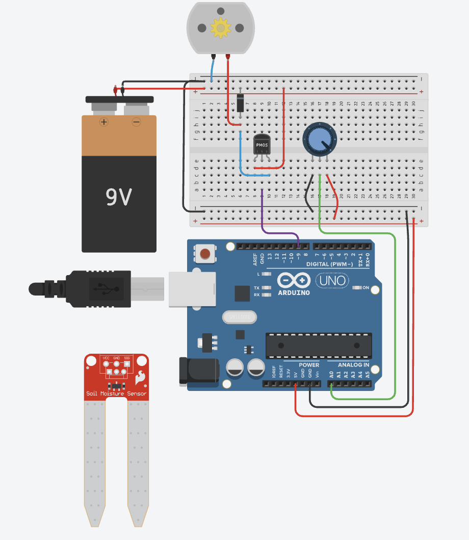
2. Hardware Wiring
| Module | Pins | Arduino Connection | Note |
|---|---|---|---|
| Soil moisture sensor (analog) | VCC / GND / AOUT | 5V / GND / A0 | Check water resistance & corrosion; calibrate raw values |
| Relay module | VCC / GND / IN | 5V / GND / D7 (example) | Many modules are LOW-active (invert logic if needed) |
| Water pump | COM / NO | Drive external PSU (5V/12V) positive lead via relay | Verify current capacity & wire gauge |
3. Example Pump Control Code
// Arduino example: Soil moisture → Pump control via relay
int sensorPin = A0;    // Soil moisture sensor (analog)
int relayPin  = 7;     // Tongling relay IN

void setup() {
  pinMode(relayPin, OUTPUT);
  Serial.begin(9600);
  digitalWrite(relayPin, HIGH); // Relay OFF initially (safety)
}

void loop() {
  int raw = analogRead(sensorPin);          // 0~1023 (UNO). ESP32: 0~4095
  int moisture = map(raw, 1023, 0, 0, 100); // Map to percentage (wet → low raw)

  Serial.print("Moisture: ");
  Serial.print(moisture);
  Serial.println(" %");

  // Simple threshold (use hysteresis in production)
  if (moisture <= 70) {
    digitalWrite(relayPin, LOW);   // Relay ON → Pump ON (LOW-active)
  } else {
    digitalWrite(relayPin, HIGH);  // Relay OFF → Pump OFF
  }

  delay(1000); // Check every 1s
}
map() or threshold logic accordingly. Consider hysteresis (e.g., ON ≤ 70%, OFF ≥ 75%) and minimum on-time for pump protection.4. Parameter Tuning
- Threshold: Start at 70% and fine-tune after field checks
- Hysteresis: e.g., ON ≤ 70%, OFF ≥ 75% to prevent frequent switching
- Minimum run time: 5–10 s to protect the pump from rapid ON/OFF
5. Safety Checklist
- Check relay rating (voltage/current) and wire gauge for the pump load
- Add a water level sensor to prevent dry running
- Stop immediately on leakage, overheating, or abnormal noise
6. Troubleshooting
- Relay works inverted: Confirm LOW-active module; flip HIGH/LOW logic
- Noisy readings: Apply averaging or EMA filter; ensure solid ground
- Always ON/OFF: Check common ground, separate supplies, and wiring
7. Next Steps (Optional)
- Integrate water level / flow sensors
- Upgrade to ESP32 for Wi-Fi and remote threshold setting
- Log and visualize moisture & pump activity (web dashboard)